Why make things move?
Electronics projects can serve many purposes but I’m sure most of us will agree that the coolest projects make things move! When we make things move we can truly automate, navigate and control the world around us. Using a servo motor is one way we can make things move and control that movement at the same time. They’re used in robots, manufacturing plants, non-invasive devices that push buttons on other devices, remote control vehicles, solar panels that track the sun and lots more devices.
What you’ll learn?
In this tutorial, you’ll learn how to cotrol a servo motor with an Arduino Uno, Nano or any other Arduino compatible board. For the purposes of hobby based electronics, this article relates to DC servo motors.
If you’re yet to choose your first Arduino board and learn the basics, I suggest starting on my introductory post series here: Arduino – Choosing your first Arduino.
Here’s what you’ll need*
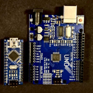
- A microcontroller – You can follow the tutorial with one of the following:
- An Arduino Uno clone board – Recommended
- An Arduino Nano clone board – Recommended
- Jumper wires – Recommended
- A servo motor – Recommended
- A motor controller board that’s compatible with servo motors – Recommended
- An external power supply of 5 Volts and at least 1 Amp – Recommended
- Power supply socket (optional) – This one is compatible with the recommended power supply.
How do servo motors work?
Servo motors are a little more complex than your standard DC motors which are also complex in their own right. Therefore, it’s worth know a little about what’s happening under the casing if you want to take full and proper control of the device. I know you’re itching to get started, so I’m not going to go into too much detail here.
Inside a servo motor there are the following key components:
- A DC motor
- The enables the motor to move
- Gears
- These convert the high speed low torque output of the DC motor to the low speed high torque output of the servo motor. This means the motor will be able to move more.
- A potentiometer
- This is used to measure the current position of the servo motor
- A comparator circuit
- This compares the current position of the servo motor with the signal being received and calculates the movement required ot bring the servo into the new position
The servo motor has three wires: Positive, Ground and Signal.
The ground and positive wires are, as you’d expect, to power the device (namely, the comparator circuit and the DC motor).
From the signal wire, the servo expects ‘pulses’ of a specific width to tell the motor what position to turn to. Simply put, a pulse is an electrical current supplied for a very short amount of time (we’re talking microseconds). When the pulse is on for a longer time, the pulsewidth is wider.
Different types and ratings of DC servo motor
There are two main types of DC servo motors: Closed Loop and Open Loop. Closed loop servos can only rotate within a range of 0 to either 90 or 180 degrees. They’re physically blocked from going any further. Open loop servos can rotate continuously through 360 degrees again and again.
I’m sure I’ve seen somewhere that some closed loop servos can be modified to become open loop servos. I’m not very confident about this as it’d require the potentiometer to be able to read the extra rotation, but it’s something for us to look into another day. Of course, I’d be grateful if you had any knowledge to share in the comments.
Key specifications to understand about your servo motor
There’s usually a lot of information available about your servo motor from the place you purchase it. For specific projects, some of the specifications may be more important than others, but for getting started, we want to pay attention to the following:
- Stall Torque
- This is the amount of force the motor can support at a specific distance from the shaft. You’ll usually see something like 2.5kgcm. This means that, at 1cm from the shaft, the mator should be able to support up to 2.5kg of force before stalling. The foce supported will halve for each further cm from the shaft.
- Operation Voltage
- This is the voltage require dfor the servo to operate. You’ll often see a range of voltages provided. Higher voltages will usually increase speed and performance, but never exceed to maximum recommended voltage.
- Most hobby servos will operate perfectly at the 5V mark. However, never power your servos directly from your Arduino pins. They’re only capable of providing a small current and so the servo is likely to cause a short circuit and potentially damage your board.
- Current Draw
- Hobby ‘micro’ servos can actually draw a lot of current and it’s recommended to allow up to 500ma current draw for each connected servo. This is for worse case scenarion, for example, the servo being under heavy enough strain to cause a stall.
Powering and connecting the motor and controller
Before we get to the code, we need to wire everything together. Let’s get started with the power supply and the motor controller board.
For a power supply, I recommend this 5V 5A supply. It’ll be more than enough, not only to follow along with this tutorial, but also to continue to use as your projects grow. You can find my recommendation here: https://theprojectlounge.co.uk/recommends/5-amp-psu/
With this supply, you can either cut the connector from the end and wire to your project directly, or buy a socket for easy connecting and disconnecting of multiple projects. The socket required for the recommended PSU is here: https://theprojectlounge.co.uk/recommends/2-1-x-5-5mm-psu-socket/
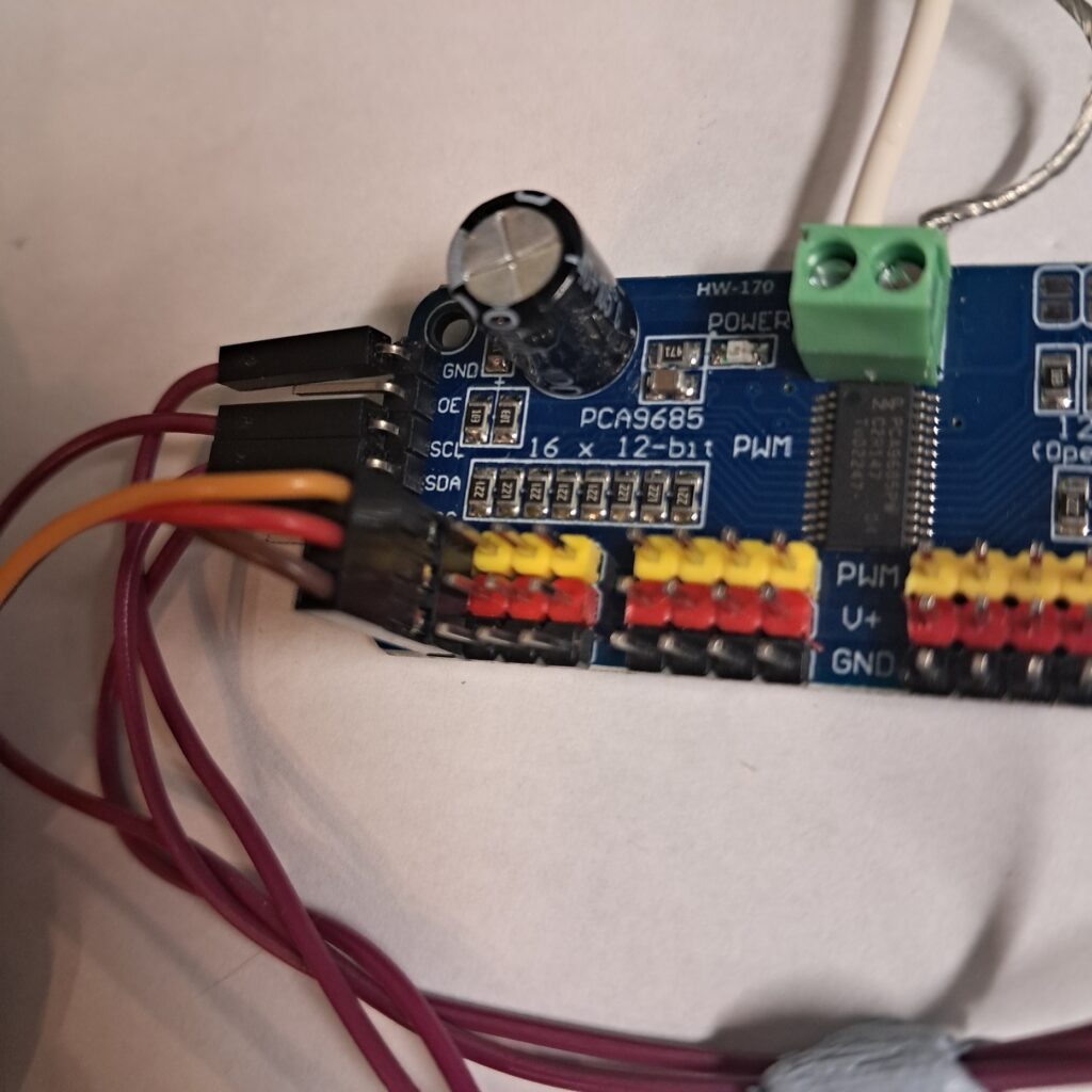
For the motor controller, I recommend the PCA9685PW. Not only does it allow simple powering of your motors with pins for easy connections, it also allows you to control up to 16 motors using the I2C interface, freeing up other pins on your microcontroller for other uses. My link to this item is: https://theprojectlounge.co.uk/recommends/pca9685pw-16-channel-servo-motor-controller/ (order a couple, mistakes are likely to be made!)
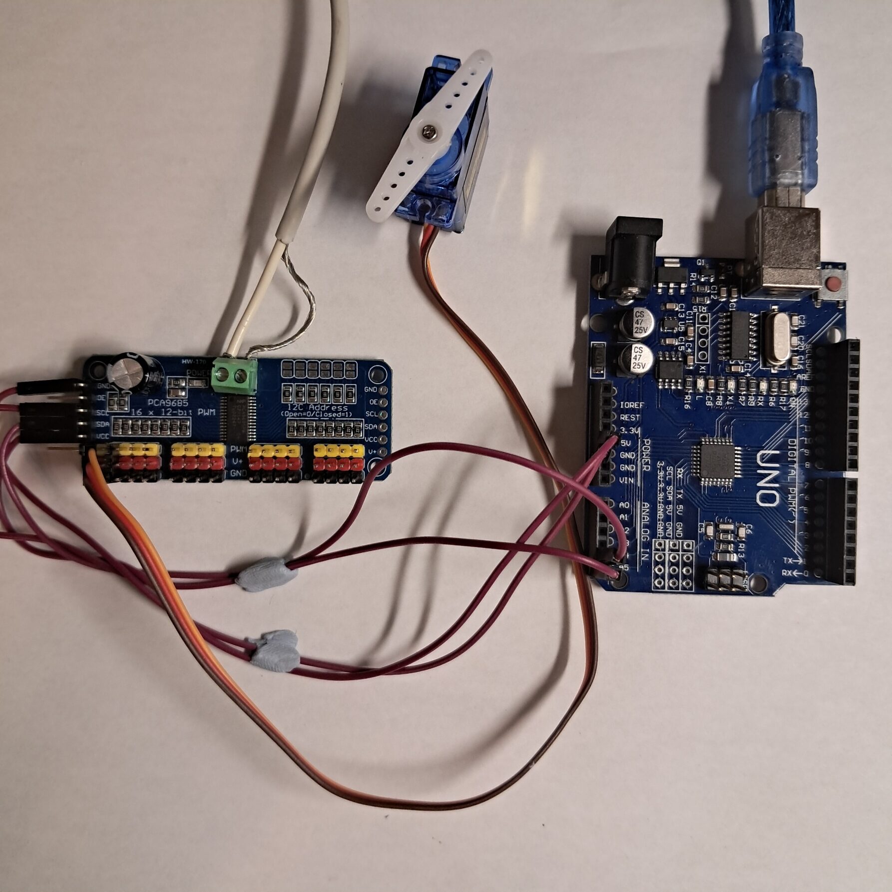
The power supply is wired directly to the terminal block on the motor controller. There is a small V+ noteded next to one side of the terminal block (next to the power light). Ensure the positive wire connects on this side. If you’re using a power supply connector, connect it here again ensuring correct polarity.
The Arduino is connected to the pins on the left in the following way:
| PCA9685 Motor Controller | Arduino Uno / Nano / Other Arduino boards |
| GND | GND |
| OE | Optional – Not used in this tutorial |
| SCL | A5 (Uno / Nano, check other boards for the correct SCL pin) |
| SDA | A4 (Uno / Nano, check other boards for the correct SDA pin) |
| VCC | 5V |
| V+ | Not Connected (DO NOT USE) |
Finally, we need to connect our servo motor. The PCA9685 has 16 servo connectors known as channels. We’re going to be working on channel 0 which is the left most channel as you look at the board with the text orientated correctly. Connect the motor so that the orange wire connects to the yellow pin, the red wire connects to the red pin and the brown wire connects to the black pin, like so:
Coding the movement with Arduino
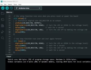
You first need to ensure you have the Adafruit PWM Servo Driver Library installed. This can be done via the library manager built into the Arduino IDE.
When I’m playing with a new Arduino toy, I always start with the example code. The example for this library, while it worked, was too clunky for an introductory blog post and even states the necessity of an oscillioscope to prepare your code. Fortunately, that wasn’t the case and so I’ve managed to get something togehter that’s much easier for us to get started with.
In an attempt to ensure you understand every line of the code, I’ve beefed up the comments in the code.
#include <Adafruit_PWMServoDriver.h>

Adafruit_PWMServoDriver pwm = Adafruit_PWMServoDriver(0x40); // Start a new motor controller board instance named "pwm" with an I2C address of 0x40 (this is the default address for the PCA9685 motor controller).

#define SERVOMIN  100 // This is the 'minimum' pulse length count (out of 4096)
#define SERVOMAX  600 // This is the 'maximum' pulse length count (out of 4096)
#define SERVO_FREQ 50 // Analog servos run at ~50 Hz updates

void setup()
{
  pwm.begin();
  pwm.setOscillatorFrequency(27000000);
  pwm.setPWMFreq(SERVO_FREQ);  // Analog servos run at ~50 Hz updates
  delay(10);
}

void loop() {
  // Move the motor to the SERVOMAX position

  // The for loop ensures the motor moves one step at a time for a smoother movement and is necessary on some servos for the request to complete successfully

  for (uint16_t pulselen = SERVOMIN; pulselen < SERVOMAX; pulselen++) {

    // In this loop, pulselen starts at SERVOMIN and increments by one until it reaches SERVOMAX.
    pwm.setPWM(0, 0, pulselen);

    // setPWM takes three arguments:
    // The first argument is the channel. It's set to 0 here as we're working on the first servo connector on the PCA9685.
    // You can change this up to 15 to work with servos on other channels / connectors.
    // The second and final arguments are times on a clock of 4096 microseconds.
    // The second argument is is when we want the electronic pulse to start.
    // We can start the pulse immediately, at 0, or we can wait.
    // The final argument is for when we want the electronic pulse to end.
    // The pulse length is the difference between the second and final arguments.
    // For most purposes, it's fine to leave the second argument at zero set the third argument to the desired pulse length.
    // The longer the pulse duration, the further the motor rotates.
    // In this example we start each pulse at 0 and end each pulse at progressively longer up to SERVOMAX.
  }

  delay(2000); // Wait 2 seconds.

  for (uint16_t pulselen = SERVOMAX; pulselen > SERVOMIN; pulselen--) {

    //In this loop, pulselen starts at SERVOMAX and decrements by one until it reaches SERVOMIN.
    pwm.setPWM(0, 0, pulselen);

    // Like above, we're working on channel 0 and each pulse starts at 0.
    // We're just changing when the pulse ends, this time  reducing the pulse length with each iteration of the loop.
  }

  delay(3000); // Wait 3 seconds.

}
The final result
If all’s gone well, you should have a servo motor under your control. This is what you should see:
It’s simple and doesn’t actually do anything useful, but the point is that you now know how to control these motors. Of course, the numbers you use to determine the positions don’t have to be hardcoded into your projects. They can come from sensors or, with the right equipment, the internet. You could move a solar panel to the brightest angle or wave a flag when your favourite team score!
*Products found for you
The spirit of this site is to introduce as many people as possible to multiple projects and hobbies. To aid that mission, I try to keep costs to a minimum for both you and me.
I’ve found some of the best products at the best available prices and linked to within this article. When you buy using these links, at no extra cost to you, you support this site. I get a small commision which I hope will eventually cover the costs of running the site. Your support is very much appreciated and I hope you have fun with your purchase.
If you find better products at better prices, please let me know and, if possible, I’ll update my links to ensure I’m always offering the best value.
What next
I have a few projects in mind and not all of them involve an Arduino and a computer, so please come back soon. If there’s anything you’d like to see featured, please leave a comment and let me know.
Thanks for reading. I really hope you found this useful!