What is serial communication?
As an Arduino beginner, all you need to know is that serial communication allows text to be transferred between your Arduino and other devices. More technically, Arduino boards use the UART (Universal Asynchronous Reception and Transmission) serial communication protocol.
We use serial communication with our Arduino to send messages to our computer and also to receive them back. This is useful when we want to communicate with a specific piece of software, but it’s most commonly used to debug code, meaning to find errors that are making our code run in a way that’s not expected).
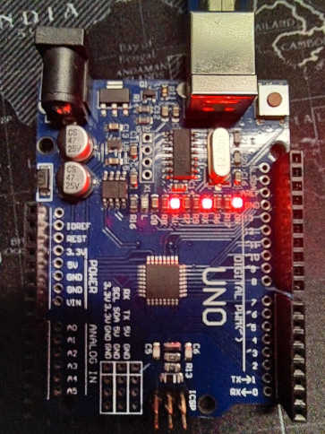
Take a look at your board. Look closely at pins 0 and 1 and you’ll see “RX” next to pin 0 and “TX” next to pin 1. This means, when the board is communicating, pin 0 receives data and pin 1 transmits data. Data reception is done by counting electronic pulses received on pin 0 relative to ground, whereas data transmission is done by sending electronic pulses via pin 1 to the receiving device.
You send serial communications from one Arduino board to another by connecting the RX pin from one board to the TX pin of the other and vice versa, that’s RX to TX and TX to RX.
The USB connection on your board also works as a serial connection to your Arduino and so, to communicate to your computer, you don’t need any extra equipment.
How to send messages from your Arduino to your computer
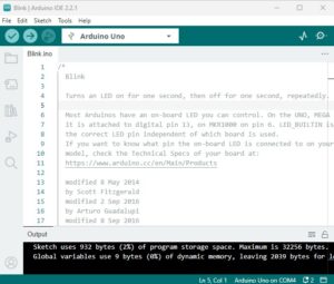
All we need to get the your Arduino board and your computer talking is a few lines of code:
void setup() {
  // initialise serial communication at 9600 bits per second:
  Serial.begin(9600);
}

void loop(){
  // send a line of text via serial communication with the Serial.println() function:
  Serial.println("Hello, World!");

  // Wait 5 seconds
  delay(5000);
}
You’ll see that we first have to initialise the communication with the Serial.begin() function. The number 9600 is the number of bits that are to be transmitted / received per second. This must be matched on the second device, otherwise the two won’t understand each other.
Next, in the loop() function, we can put the Serial.println() function anywhere we want to send a message to the computer. Here, we’re sending a line of text (otherwise known as a string). We have to surround it by quotes so that the compiler knows it’s text and not a variable name (we’ll cover that later).
You’ll be familiar with the delay() function from the previous tutorial.
How to receive serial communications from your Arduino on your computer
Serial communications are very standardised and there are multiple pieces of software that allow computers to read and display to messages received.
You’ll be pleased to know that the Arduino IDE software actually comes with a tool called “Serial Monitor”. To activate it, in the Arduino IDE, go to Tools > Serial Monitor. Ensure the baud rate matches the number you entered in the Serial.begin() function. We’ve used 9600 in the above example.
If everything’s gone to plan, you should see your message being displayed on your computer.
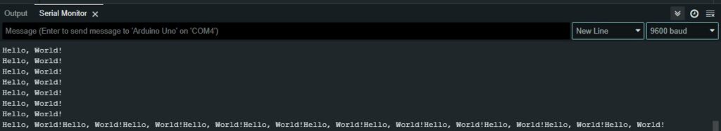
Instead of Serial.println(), you can use Serial.print(). The latter simply doesn’t automatically add a new line. The below screen snip shows the difference between the two:
Using serial communication to know what’s happening in your code
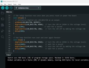
Serial communication is a great way to understand what’s happening behind the scenes on your board. Let’s go back to our blink example and add some serial communications:
// the setup function runs once when you press reset or power the board
void setup() {
  // initialize digital pin LED_BUILTIN as an output.
  pinMode(LED_BUILTIN, OUTPUT);

  // initialize serial communication at 9600 bits per second:
  Serial.begin(9600);
}

// the loop function runs over and over again forever
void loop() {
  digitalWrite(LED_BUILTIN, HIGH);  // turn the LED on (HIGH is the voltage level)
  Serial.println("LED pin is HIGH");// send a line of text via serial with Serial.println()
  delay(1000);                      // wait for a second
  digitalWrite(LED_BUILTIN, LOW);   // turn the LED off by making the voltage LOW
  Serial.println("LED pin is LOW"); // send a line of text via serial with the Serial.println()
  delay(1000);                      // wait for a second
}
As you may have figured out, this gives us a notification via the Serial Monitor everytime the light changes. This kind of feedback from the board will prove to be incredibly useful in future projects and we’ll put it to more use in the next post where we explore variables.
What next
Now that we can see what’s happening inside the Arduino, we’re in a much better place to learn, therefore we’ll look into variables and what we can do with them next (Arduino – What variables are and how to use them).
I recommend taking a look through the other posts in this series:
- Choosing your first Arduino
- How To Install, Set Up and Upload Code
- How to code your Arduino
- What variables are and how to use them
- How to use operators
Further information relating to Arduino’s use of serial communication, including a list of available functions, can be found here: https://www.arduino.cc/reference/en/language/functions/communication/serial/